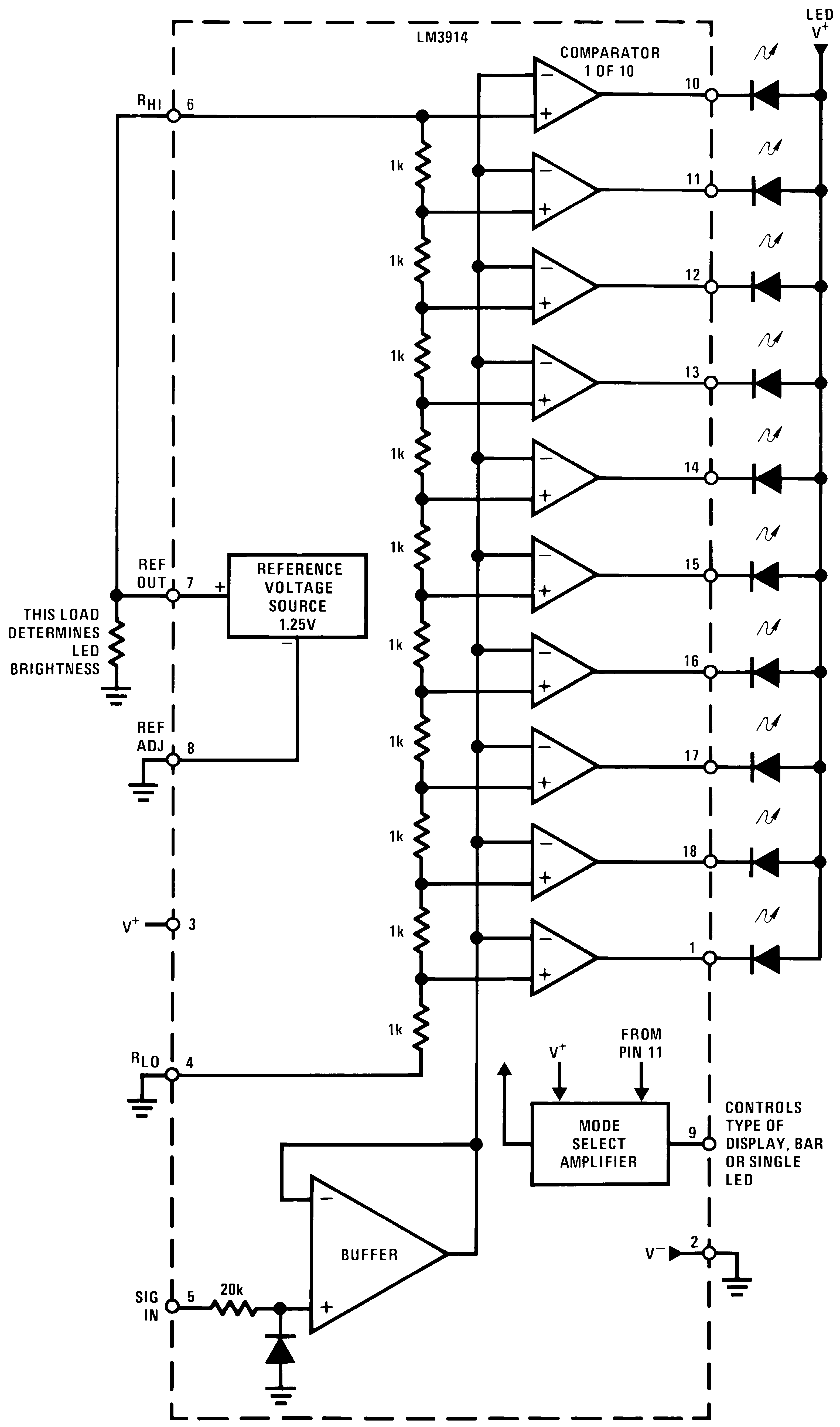
Operating Principle
The chip contains a voltage divider with a comparator at each resistor.
The points between the resistors of the voltage divider go to the + side of each comparator
The input signal goes to the - side of each comparator.
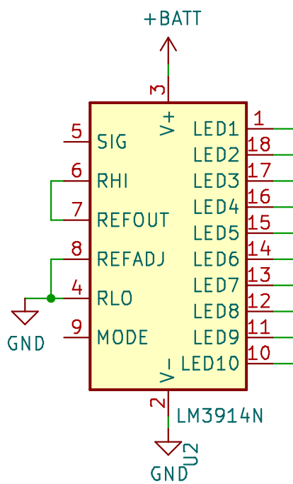
Pins
| Number |
Symbol |
Name |
| 4 |
RLO |
Divider (low end) |
| 5 |
SIG |
Signal Input |
| 6 |
RHI |
Divider (high end) |
| 7 |
REFOUT |
Reference Output |
| 8 |
REFADJ |
Reference Adjust |
| 9 |
MODE |
Mode Select |
REFADJ and REFOUT
The chip provides a stable voltage of 1.25 Volt between REFADJ and REFOUT.
RLO
The RLO input goes to the low end of the voltage divider.
If we want the lowest measured voltage to be 0V, connect pin 4 to ground.
If we want the lowest measured voltage to be higher than 0V, connect pin 4 to a voltage divider.
RHI
The RHI input goes to the high end of the voltage divider.
SIG
The SIG input signal goes to the - side of each comparator.