

|
LM3914 circuit_04 |

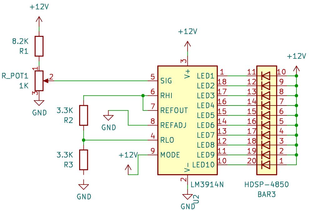
In this circuit, we want to display a voltage range between 0.625 - 1.25 V.
The battery voltage is 12 V.
The voltage divider with R1 and R_POT1 limits the maximum voltage at SIG to
We want to limit the input voltage at SIG to 1.25 V.
A trim potentiometer with a value of 1K Ω is easily available.
With these choices, the value for R1 becomes
An 8.6K Ω resistor is not easy to find, but with an 8.2K Ω resistor we get
If we set the voltage at RLO to 0.625 V, the comparators will not start to turn on the outputs until the voltage at SIG reaches 0.625 V.
This can be accomplished by adding a voltage divider with the values
The upper end of the voltage divider is connected to REFOUT which is 1.25 V.
The lower end of the voltage divider is connected to ground.